Assembling your Dremel Project Table
Julian examines and assembles a Dremel Project Table…
Our Project Table arrived in a box that was 17 inches by 11.5 inches by 3.5 inches in size and so would be easy to carry if I had bought it from a hardware or hobby store. It was a nice afternoon, so I thought I would assemble the new tool in the garden.
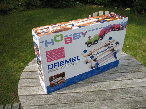
Opening the box I found the components neatly organised and held in place with cardboard:
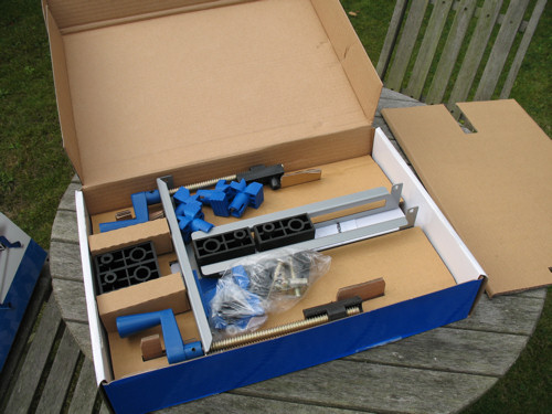
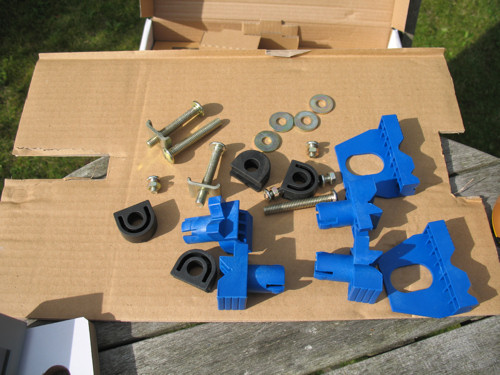
After a short rummage around, I found the instructions (which are all diagrams) and took out the components ready to start work:
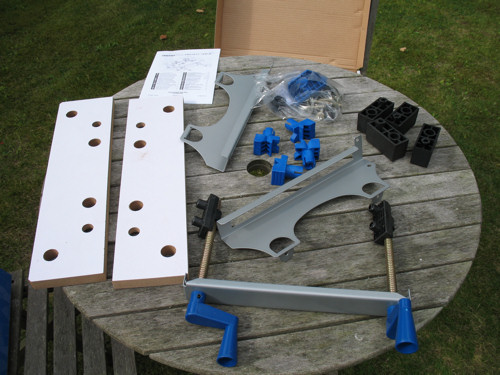
When assembled, the project table will be roughly 15 inches by 12 inches by 5 inches, so my small garden table is easily big enough to be my work area for the next 20 minutes (the instructions state assembly will take 20 minutes and this is an accurate estimate).
You will need two tools in order to make the assembly; namely a cross-head (Philips) screw driver and an adjustable spanner (or a small spanner that can tighten nuts of about one third of an inch). I don’t have any small spanners, so I had to rely on an adjustable spanner, which was in reality, a little too large for this project, so I would certainly recommend a small adjustable spanner. Your screwdriver will also need to be fairly large.
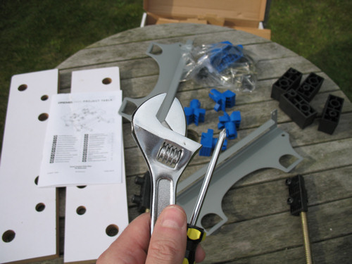
All the ‘small parts’ of the project table:
The first part of the instructions covers the assembly of the basic frame of the tool and this is the fiddliest part of the whole project. It involves connecting the front plate (with the two winding handles) to the two side parts on which the sliding jaw will eventually sit.
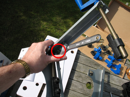
Having slotted the left side into the front plate and dropping the top bolt through the hole, I then turned the two pieces upside down so that I could hold the nut with the adjustable spanner and screw the bolt tight. In this picture, the spanner is holding the nut:
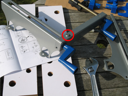
After tightening and turning the right way up, you can see where the bolt goes:
Before inserting the other nut and bolt that will attach the side to the frame, ensure the slider is positioned correctly. There are two ‘nodules’ that need to be in place and once the second nut and bolt is added, you won’t be able to position the slider correctly. See this picture:
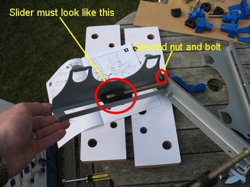
The nut and bolt that connects on the side of the project table proved the most difficult for me to tighten due to the size of my adjustable spanner (slightly too large for this task), I tightened the assembly by holding the nut with the spanner and turning the screwdriver:
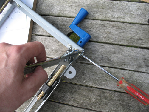
Again – ensure the slider is correctly positioned before tightening.
That completed the first part of the instructions and the frame looked like this (and I was half way through my cup of tea!):
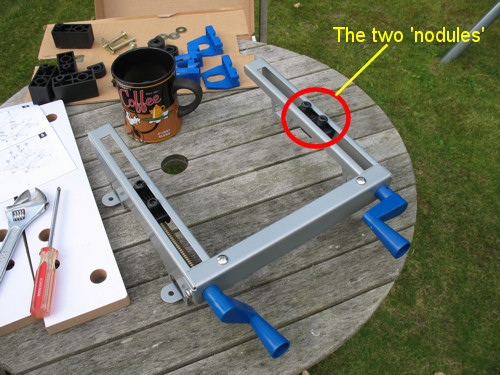
The next part of the instructions was by far the easiest part – attaching the rubber feet:
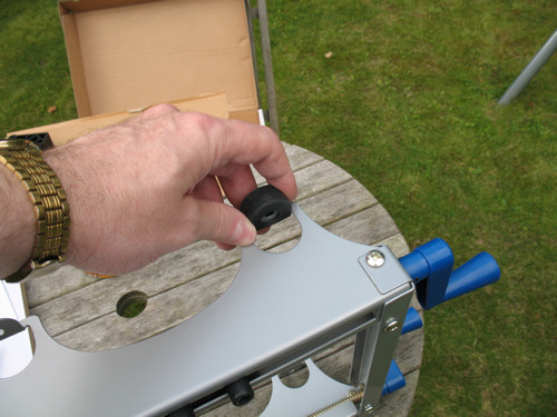
There is a hole through both the rubber foot and the metal frame which is useful if you intend attaching the project table to a workbench. The rubber feet simply slide on.
Once in place the rubber foot should look like this:
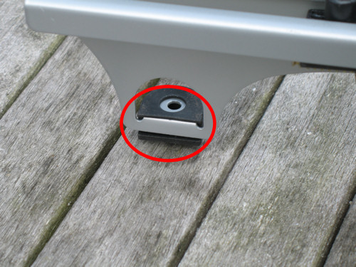
All four feet now on:
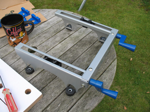
Only two parts of the instructions left to follow and both very easy. The first was the attaching of the jaws to the frame and the first thing you will need to do is wind the sliders back toward the blue handles to give you room to attach both jaws easily. Leave about half an inch then simply place the jaw holders (for want of a better name) on the sliders. They fit onto the sliders easily:
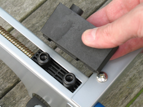
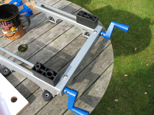
Note the large and small holes and their position.
Now lie the moving jaw on the top of the holders – a part of the holder will fit through a hole in the jaw. Note that the holders are simply sitting on the frame at this point, so it is easy to knock them over.
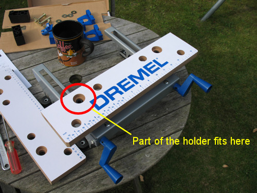
Now use two of the long bolts with washers to attach the jaw to the frame:
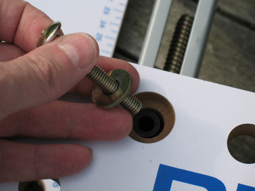
You won’t use a nut for these bolts as the slider is designed to receive the bolt.
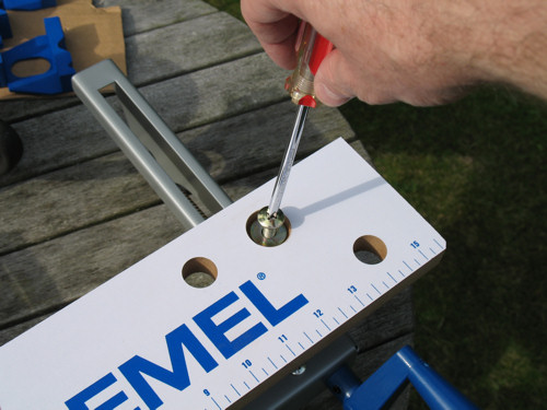
The sliding jaw is now attached:
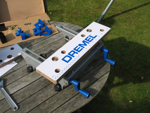
Now perform a similar (but slightly fiddly) task to attach the rear fixed jaw to the frame. First, place the jaw holders on the frame as far back as you can place them:
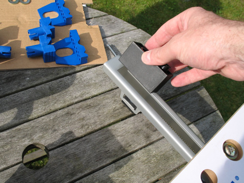
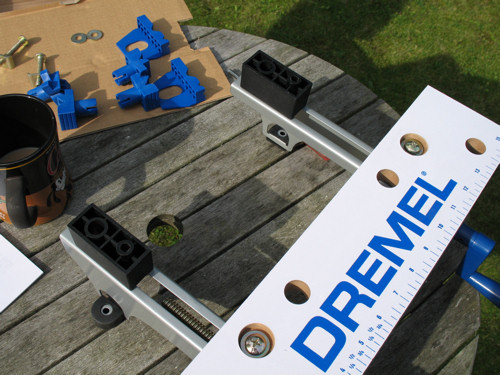 Note which way round the holders should be.
You will need to screw the bolt into a fastening plate, which slots into the underside of the metal frame. This picture is purely to show what is required to hold the jaw in place, you will need to place it over the holders before using the bolt. Also note which way up the fastening plate should be:
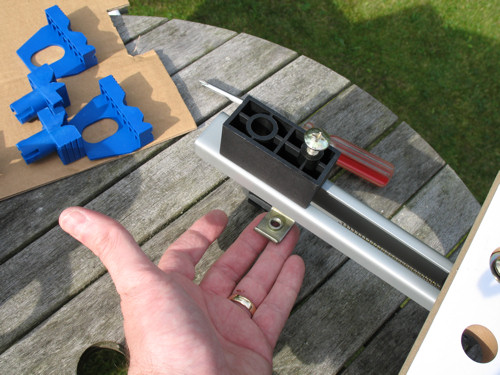
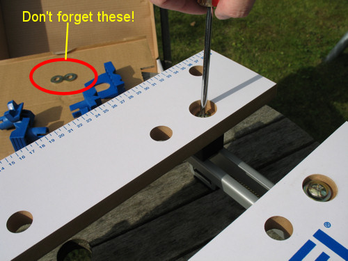
In my enthusiasm to complete the task, I managed to screw in the bolts without using the washers – don’t make this mistake as the jaw will simply come off!
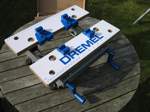
Both jaws now in place (and with all washers being used!):
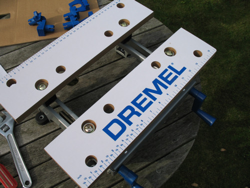
The final part of the instructions was simply to place the jaw attachments which can be moved and removed depending upon the task at hand:
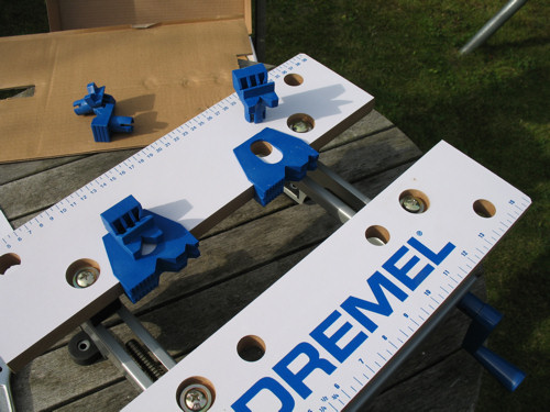
All complete:
You can obtain the Project Table from hobby stores or from Amazon:


 Click
Click